
FINTUBE DIVISION
Fully welded Rosink finned tubes
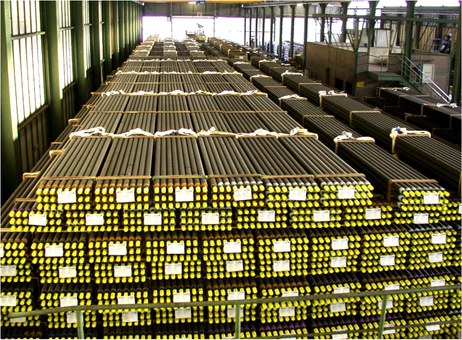
Rosink-Werkstätten has been worldwide developing, producing and distributing spiral and double H finned tubes made of steel since 1985 and has developed into one of the leading companies in this field. Finned tubes are the main components of economizers, heat recovery boilers and numerous other industrial heat exchanger applications. They are used for heat recovery in gas and steam power plants, district heating power plants, reactors and furnaces for the chemical and petrochemical industries. Renowned international boiler manufacturers, chemical and petrochemical companies as well as engineering and project development companies source their finned tubes from Rosink and rely on the company’s certified quality and comprehensive service.
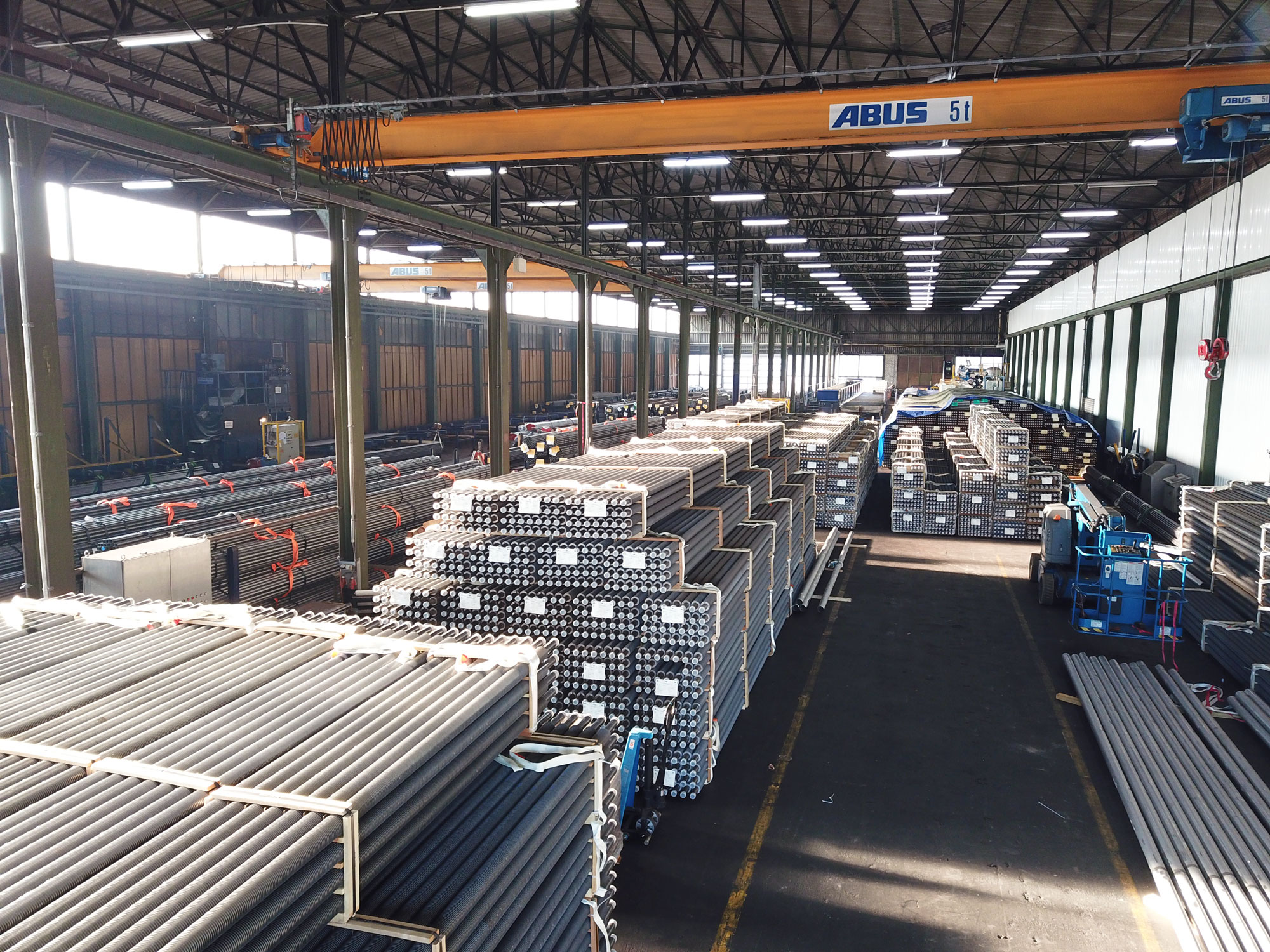
30,000 tons finned tube production capacity per year
According to developments in the aforementioned industries, the annual production output was steadily increased. More than 10 production machines are available for the production of finned tubes. This includes several HF machines and resistance projection welding machines. Thus, customer requirements can be met quickly, reliably and flexibly, regardless of the quantity.
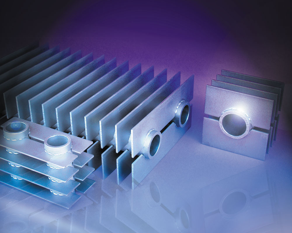
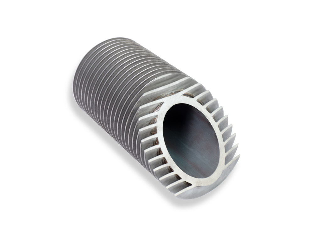
Single or double
Rosink H finned tubes
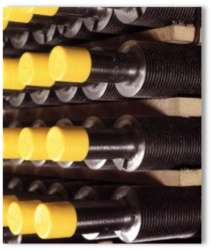
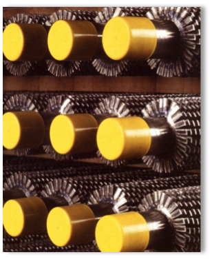
H finned tubes are produced as single or double tubes according to customer specifications. They are especially suitable for dusty flue gases, e.g. economizers in:
- Biomass plants
- Coal fired units
- Oil fired units
- Waste to energy plants
A straight flue gas flow and an appropriate fin spacing reduce possible soot deposits on the heating surfaces and facilitate cleaning and maintenance work.
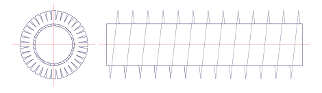
Standard finning options for double finned tubes:

| D | L(max) | L2(min) | h | w | c | t | td | p |
|---|---|---|---|---|---|---|---|---|
| mm | mm | mm | mm | mm | mm | mm | mm | mm |
| 31,8 | 16000 | 100 | 125 | 27 | 6 | 2 + 2,5 | 65 | 9 – 40 |
| 31,8 | 16000 | 100 | 145 | 32 | 6 | 2 + 2,5 | 75 | 9 – 40 |
| 31,8 | 16000 | 100 | 150 | 32 | 6 | 2 + 2,5 | 80 | 9 – 40 |
| 33,7 | 16000 | 100 | 145 | 32 | 6 | 2 + 2,5 | 75 | 9 – 40 |
| 38,0 | 16000 | 100 | 195 | 42,5 | 10 | 2 + 2,5 | 100 | 9 – 40 |
| 38,0 | 16000 | 100 | 145 | 32 | 6 | 2 + 2,5 | 75 | 9 – 40 |
| 38,0 | 16000 | 100 | 180 | 40 | 10 | 2 + 2,5 | 92 | 9 – 40 |
| 42,4 | 16000 | 100 | 235 | 52,5 | 10 | 2 + 2,5 | 120 | 9 – 40 |
| 44,5 | 16000 | 100 | 215 | 50 | 10 | 2 + 2,5 | 110 | 9 – 40 |
| 44,5 | 16000 | 100 | 176 | 39 | 10 | 2 + 2,5 | 90 | 9 – 40 |
| 44,5 | 16000 | 100 | 196 | 45 | 6 | 2 + 2,5 | 100 | 9 – 40 |
| 48,3 | 16000 | 100 | 195 | 42,5 | 10 | 2 + 2,5 | 100 | 9 – 40 |
QUALIFIED FINNING METHOD
High-frequency helically finned tubes
Rosink spiral finned tubes are the main components of economizers, heat recovery boilers and numerous other industrial heat exchanger applications. They are available with solid fins or with segmented fins. The geometry of Rosink finned tubes is adapted to specific customer requirements and flue gas characteristics.
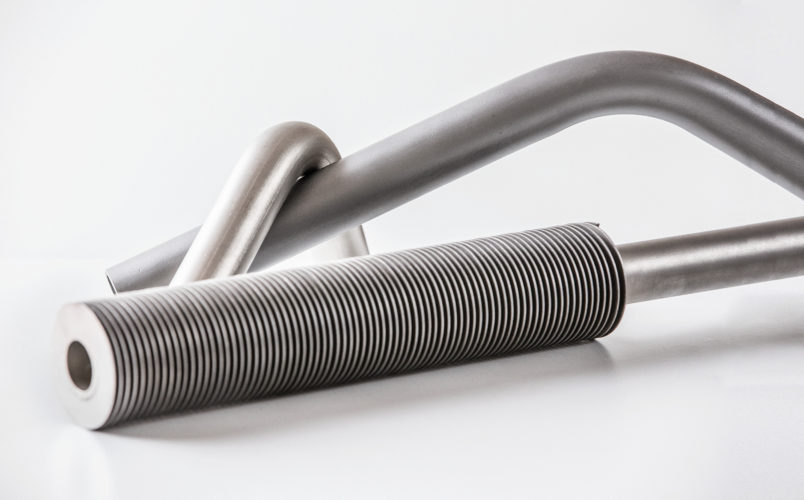
Solid fins
The fins are helical wounded onto the tube and the fin is continuously fully welded to the tube.
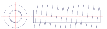
Tube with solid fins
Serrated fins
The fin strip is slotted at short intervals. A remaining height of 5 mm is left unslotted, which forms the continuous fin base. When the finstrip is helically wound onto the tube the serrated part of the finstrip devides at the outer end thus forming rectangular segments.
Tube with segmented fins
Standard fin materials
Almost any combination of tube and fin can be processed. However, the most commonly used fin materials are:
| ASME | ASTM | EN | fin thickness | fintip temperature |
|---|---|---|---|---|
| SA1008 | 1.0338 (DC04) | 0,8mm up to 3,0mm | max. 490° C | |
| A240 TP410S | 1.4000 (X6Cr13) | 0,8mm up to 3,0mm | max. 650° C | |
| A240 TP409 | 1.4512 (X2CrTi12) | 0,8mm up to 3,0mm | max. 650° C | |
| A240 TP304 | 1.4301 (X5CrNi18-10) | 0,8mm up to 3,0mm | max. 850° C | |
| A312 TP16L | 1.4404 (X2CrNiMo17-12-2) | 0,8mm up to 3,0mm | max. 850° C | |
| A312 TP316 Ti | 1.4571 (X6CrNiMoTi17-12-2) | 0,8mm up to 3,0mm | max. 850° C | |
| A312 TP310S | 1.4845 (X8CrNi25-21) | 0,8mm up to 3,0mm | max. 1000° C |
Standard finning options for helically finned tubes:
| ASA normal pipe |
OD | Fin height min./max. NOH I-fin solid |
Fin height min./max. HF I-fin solid |
Fin height min./max. NOH I-fin serrated |
Fin height min./max. HF I-fin serrated |
|---|---|---|---|---|---|
| 1/2″ | 21,3 mm | 6,5 – 10 mm | 6,5 – 10 mm | 13 – 32 mm | 13 – 32 mm |
| 25 mm | 6,5 – 13 mm | 6,5 – 13 mm | |||
| 25,4 mm | 6,5 – 13 mm | 6,5 – 13 mm | |||
| 3/4″ | 26,9 mm | 6,5 – 14 mm | 6,5 – 14 mm | ||
| 31,8 mm | 6,5 – 19 mm | 6,5 – 19 mm | |||
| 1″ | 33,7 mm | 6,5 – 19 mm | 6,5 – 19 mm | ||
| 38 mm | 6,5 – 25 mm | 6,5 – 25 mm | |||
| 1 1/4″ | 42,4 mm | 6,5 – 27 mm | 6,5 – 27 mm | ||
| 44,5 mm | 6,5 – 29 mm | 6,5 – 29 mm | |||
| 1 1/2″ | 48,3 mm | 6,5 – 31 mm | 6,5 – 31 mm | ||
| 51 mm | 6,5 – 32 mm | 6,5 – 32 mm | |||
| 57 mm | 6,5 – 32 mm | 6,5 – 32 mm | |||
| 2″ | 60,3 mm | 6,5 – 32 mm | 6,5 – 32 mm | ||
| 2 1/2″ | 76,1 mm | 6,5 – 32 mm | 6,5 – 32 mm | ||
| 3 | 88,9 mm | 6,5 – 32 mm | 6,5 – 32 mm | ||
| 101,6 mm | 6,5 – 38 mm | 6,5 – 32 mm | |||
| 4″ | 114,3 mm | 6,5 – 38 mm | 6,5 – 32 mm | ||
| 5″ | 139,7 mm | 6,5 – 38 mm | 6,5 – 32 mm | ||
| 141,3 mm | 6,5 – 38 mm | 6,5 – 32 mm | |||
| 6″ | 168,3 mm | 6,5 – 38 mm | 6,5 – 32 mm | ||
| 8″ | 219,1 mm | 6,5 – 38 mm | 6,5 – 32 mm |
The fin thickness can be selected in 0.05 mm increments. The maximum fin thickness is 3.0 mm for solid fins. For segmented fins, the maximum fin strength is 2.0 mm for carbon steel. Other dimensions are available on request.
| max. fin density for fin thickness: |
I-FIns |
|---|---|
| 1,25 mm | 303 R/m |
| 1,0 mm | 310 R/m |
| 0,9 mm | 320 R/m |
| 0,8 mm | 440 R/m |

Rene Boone
Head of Fintube Division
Phone
+49 59218820-22
Norbert Hassing
Head of Heat Exchanger Division
Norbert Hassing
Head of Heat Exchanger Division
Find Us
Otto-Hahn-Str. 23
48529 Nordhorn
Germany