
Boiler Cleaning
Boiler Cleaning Systems
The cleaning concept of Rosink-Werkstätten
The Cleaning Systems Division of Rosink Werkstätten has been designing and producing a full line of Heat Transfer Surface Cleaning products since 1995. The range of products includes all types required for the cleaning of heating surfaces in power stations, heating and industrials boilers and incinerators.
Heat Transfer Surface Cleaning covers the design and project development of soot blowers, water cannons, water spraying systems, rapping systems and shot cleaning systems. These various systems clean the heat transfer surfaces during operation and maintain the efficiency, increase the continuous operating time of the boiler plants considerably and reduce the manual cleaning effort to a minimum.
Heating surfaces continuously cleaned according to the cleaning concept of Rosink-Werkstätten will increase the boiler running time and optimize its efficiency considerably. A comprehensive cleaning concept solves the problem of the flue gas temperature increasing in the convection part and also for the radiation paths.
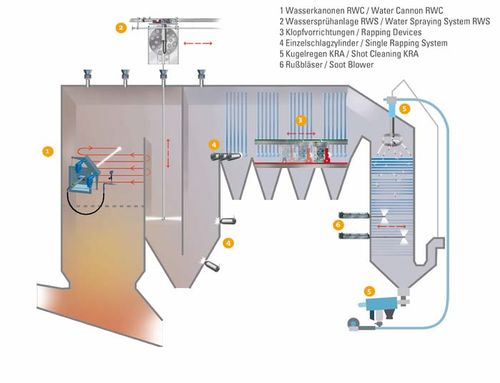
Boiler Cleaning Systems for Waste and Biomass Incineration Plants
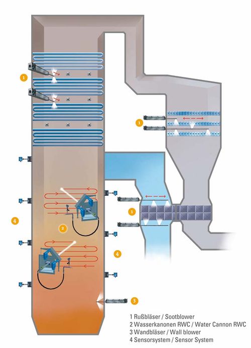
Boiler Cleaning Systems for coal-fired Power Plants and Giant Industrial Boilers
Various types
Soot Blowers
Depending on requirement and availability, steam, compressed air and water are possible cleaning media for the soot blowers. The cleaning medium under pressure is converted into velocity in the nozzles. The kinetic energy of the blowing jet cleans the heating surfaces.
Rosink-Werkstätten can offer various soot blower types appropriate for the selected purpose. All Rosink-Werkstätten soot blowers are designed and manufactured at our plants in Nordhorn/Germany.
Long Retractable Blower

Long Retractable Blower, LSB II
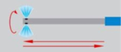
The blowing tube is moved completely into and out of the boiler with a 360° helical movement. Cleaning takes place by two opposite nozzles using steam or air. Long retractable sootblowers are mainly applied in case of high flue gas temperatures above 500°C.
Rosink-Werkstätten’s long retractable sootblowers are equipped with a staggered blowing jet as standard and stand out due to a sturdy and durable steel construction.
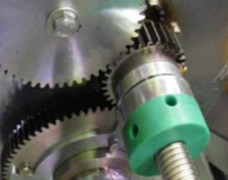
Long Retractable Blower, LSB III
As for the LSBII the blowing tube is moved completely into and out of the boiler with a 360° helical movement. The LSB III is applied in case of travels larger than 4800 mm and is particularly suitable for large boiler systems.
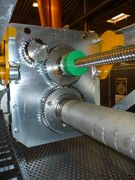
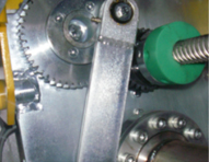
It has a special drive concept with toothed rack and chain drive as well as a special frame. The long blowtube is guided by specific tube supports.
Model details
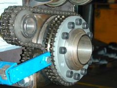
Cain LSB III
tack drive LSB III
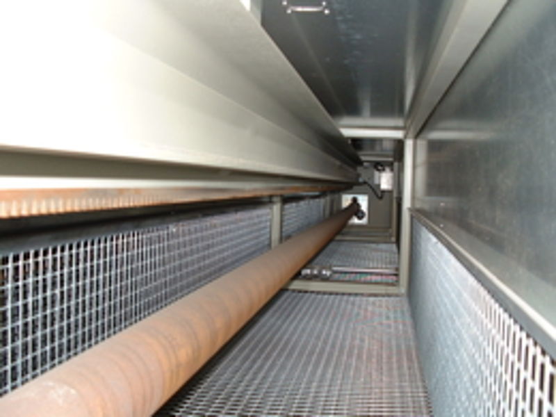
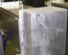
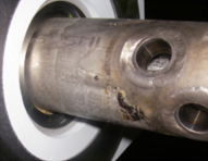
soot blower lance
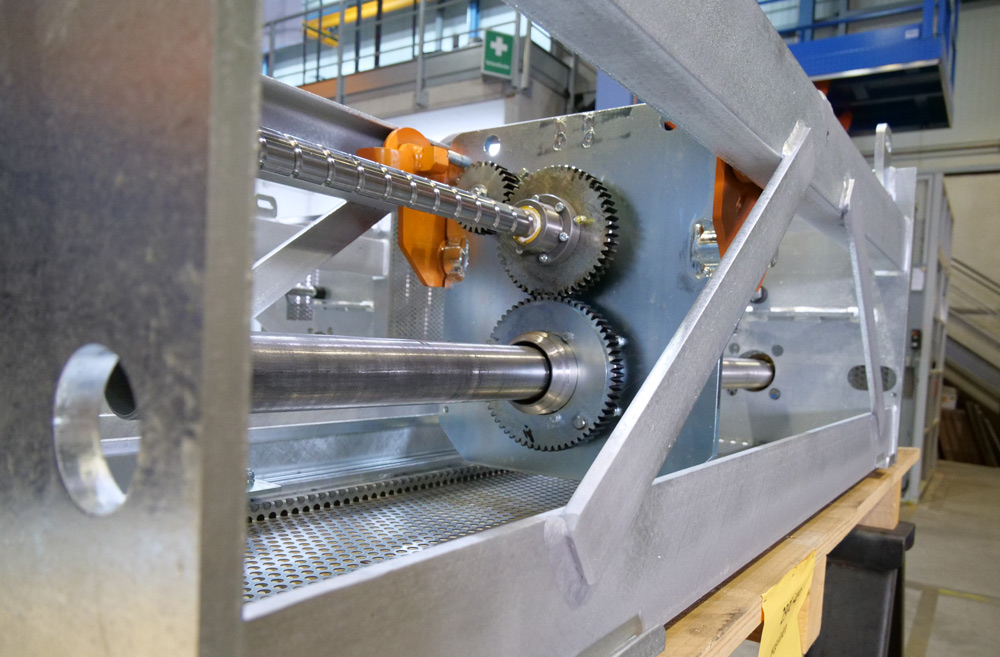
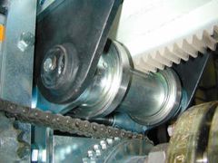
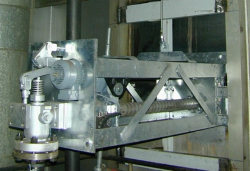
spindledrive LSB II
Short Retractable Blower
A part of the blowing tube of the short retractable sootblower remains inside the boiler. The other part is situated outside the boiler. For cleaning the exterior part is moved into the boiler with a 360° helical movement.
The Short Retractable Blower is mainly applied in case of flue gas temperatures up to approx. 500°C. Cleaning takes place by means of a selected number of nozzles using steam or air.
The part of the blowing tube located inside the boiler is guided and fixed on the tube bundles with roller supports.
blowing tube support inside the boiler
blowing tube carriage short retratable soot blower
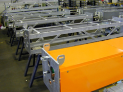
soot blowers in workshop
Rake Blower, TB

The rake blower TB has a blowing rake that can be axially shifted and is equipped with several transverse tubes. These transverse tubes are provided with nozzles directed perpendicular to the tube/fin lanes.
For the blowing process the blowing rake is moved axially back and forth by means of the motor drive, so that the flue gas pass is cleaned from deposits and ashes.
The blowing rake is guided by means of lateral or central guiding rails or by guiding tubes with lift-off protection.
Model examples
Rotary Blower, DB
The rotary blower DB is equipped with a nozzle tube and the nozzles are directed at the tube banks. By the rotary movement of the nozzle tube during the blowing process the flue gas passes are cleaned from deposits and ashes. The angle of rotation can be adjusted to the boiler situation.
The nozzle tube remains in the flue gas flow and is protected against deflection by means of tube supports.
The material is selected according to the flue gas temperatures.
Rotary blowers clean with steam or air and are applied in smaller boilers with slight fouling and little space.
Model details
wall box
side view-opened
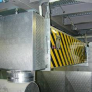
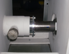
Wall blower

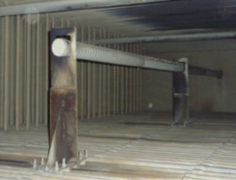
The wall blower WB is equipped with a blowing head located in the wall box while in idle mode so that it is protected against too strong heat impacts. During the blowing process the blowing head is moved out of the wall box and cleans a defined part of the rear heating surfaces from deposits.
The wall blower can be applied at nearly any flue gas temperature that may occur in firing chambers. The blowing head is made of a highly temperature-resistant material. The configuration of the blowing head is adjusted to the respective job requirements.
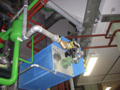
Drive system and covering
drive system
protective covering
onsite installation
Special Blowers: Oscillating Soot Blower, PB and Dual-media Soot Blower, ZB
Rosink also designs and manufactures special blower models taking into consideration the specific service conditions, e. g. soot blowers with oscillating drive or dual-media soot blowers.
Nozzle head with two staggered nozzles
custom execution oscillationg soot blower (SPB, LPB)
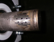
Nozzle head with equalizing holes
For rough Conditions
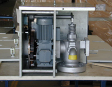
Water Cannon RWC-HD
Rosink-Werkstätten’s Water Canon RWC-HD is the ideal solution for the rough service conditions in power stations with an extremely high dust exposure and thermal load. It is especially suited to reduce excessive fouling hence reducing non-operation periods considerably.
The opposite boiler wall and the side walls are cleaned by a concentrated water jet applied in preset meandering patterns during operation. The water jet penetrates the top layer of the deposits. Due to the vaporization energy even hard-to-remove deposits flake off the boiler walls. The heavy-duty supporting structure and the easily exchangeable, low-cost drive units are designed easy to service and are located at a safe distance from the boiler.
Wet Cleaning
Water Spraying System RWS
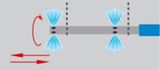
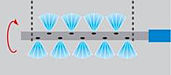
The Rosink-Werkstätten Water Spraying System RWS also called „wet cleaning“ was specifically designed for the cleaning of those parts of the boiler that have been difficult to access so far. This is especially the case for open passes of incinerators and their platen heating surfaces in the radiation path.
The simple and proven cleaning is carried out by four staggered water outlet nozzles that are offset by 90 degrees in two different levels of a nozzle head. In order to achieve a proper and complete cleaning, the nozzle head is swiveled approx. 90° around the vertical axis and moved down and up, so the jets of water are describing a helical path in sectionally different levels during the cleaning process on the boiler wall corresponding to the respective boiler symmetry.
The special feature of this solution is the special flexible hose that is lowered from the swiveling drum located above the insertion gate nozzle on the top of the boiler. Due to the swiveling movement, the nozzle head is rotating during travelling into the boiler. This leads to significantly lower friction and lower wear of the hose. This is clearly the best solution especially for bended feeding systems.
Even existing systems can be retrofitted with the Rosink-Werkstätten Water Spraying System without major modifications. An adjustment of the pressure and the amount of water and the selection of appropriate nozzles ensures that despite abrasive cleaning of the deposits the cleaning does not lead to increased wear of the boiler walls.
Online cleaning without cleaning media
Rapping Systems
The rapping systems of Rosink-Werkstätten are mainly used in waste incinerators with horizontal convection pass. Suspended evaporators, superheaters and economizers are cleaned by means of rapping.
Pneumatic cylinders or mechanical hammers hit on the reinforced caps of horizontally arranged headers. The impact energy applied causes the vertically suspended heating surfaces to vibrate and removes the deposits.
Pneumatic Rapping Systems pKL
The pneumatic rapping gear type pKL is an automatically operating online cleaning system. It cleans the heating surfaces of a boiler by rapping through specially formed rams on the lower headers. It is mainly used in case of horizontal boiler passes with suspended economizers.
The boiler walls are provided with equispaced rams resting against the bottom of the headers of the tube banks. One or several rapping carriages are moved from ram to ram. Depending on the arrangement of the tube bundles they are equipped with one or two superposed impact cylinders.
These special pneumatic impact cylinders rap on the reinforced caps of horizontally arranged headers. The impact energy applied causes the vertically suspended heating surfaces to vibrate and removes the deposits. Especially when there are numerous rapping points the cleaning by means of a rapping carriage is the more efficient and economical solution!
Rosink-Werkstätten Rapping Systems stand out due to a rugged design, low maintenance requirements as well as a less spare parts storage.
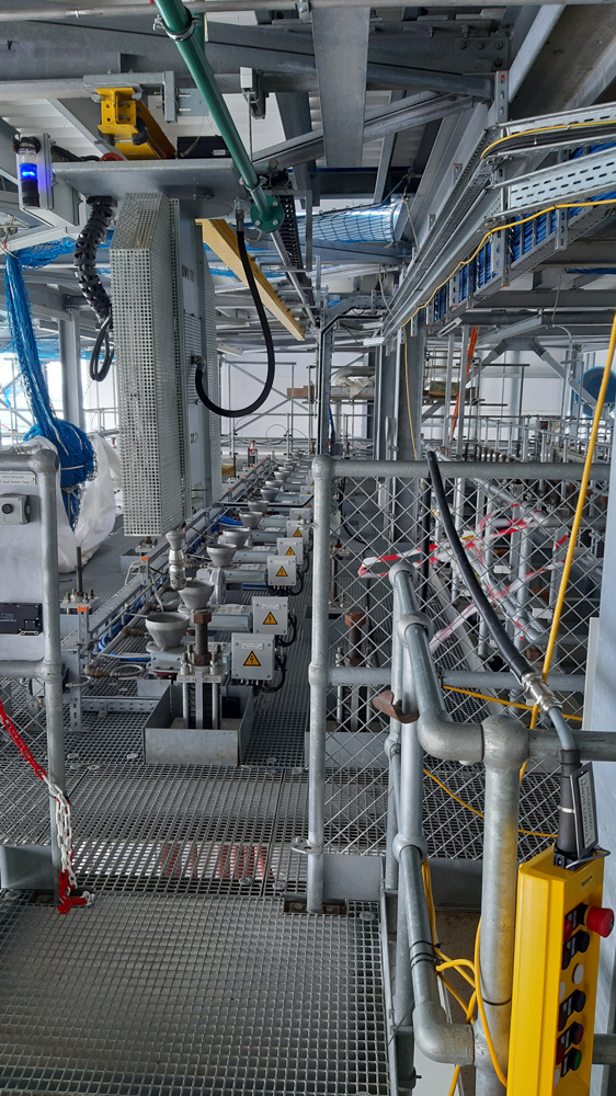
Rosink-Werkstätten Single Rapping System SRS
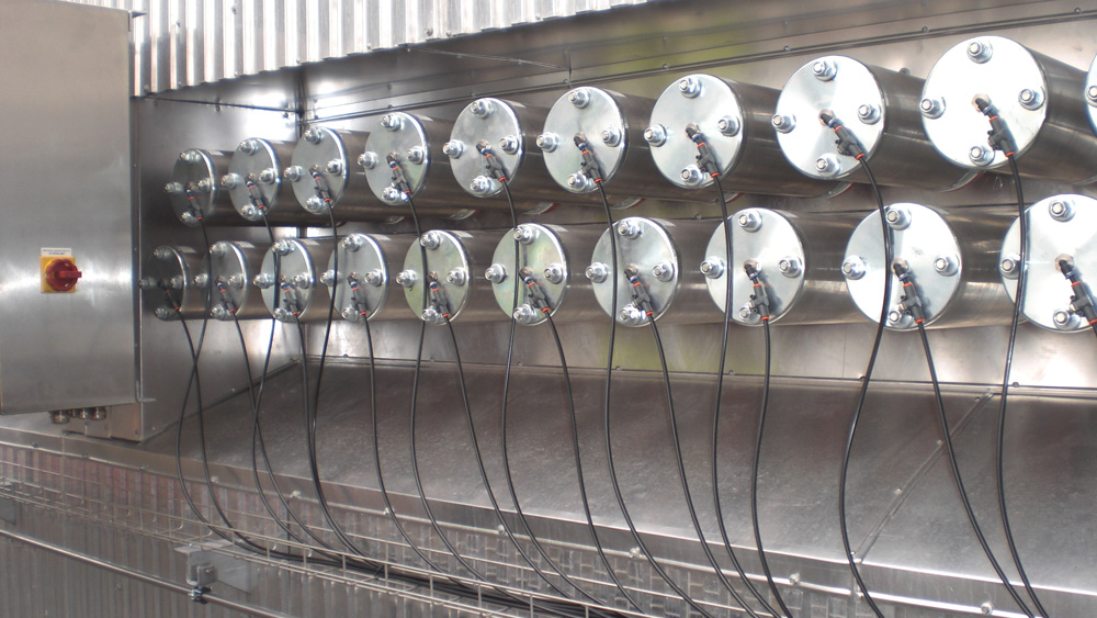
The pneumatic Rosink-Werkstätten rapping system SRS using single rapping cylinders is an automatically operating online cleaning system installed to increase the continuous operating time of boilers.
The boiler walls are provided with equispaced rams resting against the bottom of the headers of the tube banks. Each ram is provided with a compact Rosink-Werkstätten SRS single rapping cylinder used to rap on the reinforced caps of horizontally arranged headers. The impact energy applied causes the vertically suspended heating surfaces to vibrate in order to remove the deposits.
Advantages of the compact Rosink-Werkstätten Single Rapping Cylinder SRS:
- Rapping points can be activated repeatedly in succession
- Rapping points can be selected or deselected for an individually attuned cleaning
- The impact energy can be adjusted to the degree of fouling
- Individual pulse of 3 up to 8 bar for each rapping point
- One-hose technology
- No sealing air required
- No additional power supply for the cylinder
- No noise-protective enclosure required
- Spring reset
- Visual inspection of the rams – simple maintenance
- Space-saving and easy to mount
- Low installation costs
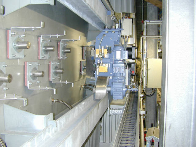
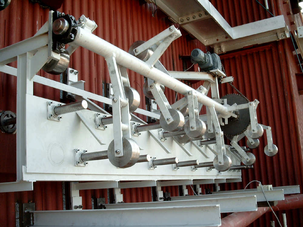
Mechanical Rapping Systems mKL
The mechanical rapping system type Rosink-Werkstätten-mKL is an automatically operating “online” cleaning system. It cleans the heating surfaces of a boiler by rapping against specially formed rams. It is mainly used for horizontal boiler passes with suspended evaporators, superheaters and economizers.
The boiler walls are provided with equispaced rams resting against the header bottom of the tube banks. All rams of a boiler side are equipped with this mechanical falling hammer. Along each side of the boiler pass these hammers are mounted on a rotating shaft. All rams need to be in a line. The impact energy applied by the mechanical hammer causes the vertically suspended heating surfaces to vibrate in order to remove the deposits. The impact energy depends on the weight of the mechanical hammer and will be designed project-specific, for example 6-14 kg per each.
Special Distribution
Shot Cleaning Systems
Rosink-Werkstätten cannot only design and realize new plants but also assure the supply of spare parts for existing FEG shot cleaning systems.
During shot cleaning, small mild steel balls are pneumatically transported into the upper boiler section. Via a special distribution system the balls fall through the horizontal tube banks of the heating surfaces by gravity. Through the impact energy of the balls the deposits are removed from the heating surfaces and separated and reused at the dust outlet.
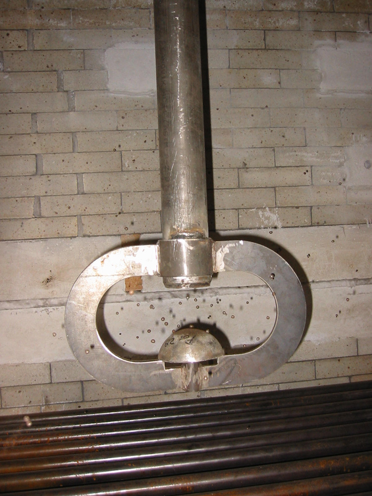
calotte inside Boiler
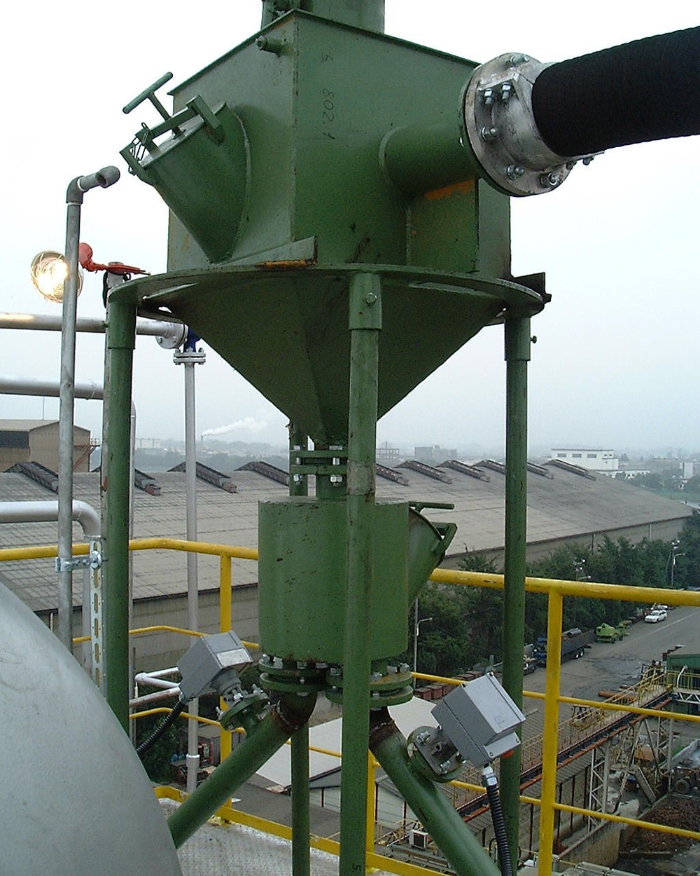
example of an installation
Volker Hummel
Authorized Signatory
Head of Cleaning System Division
Phone
+49 59218820-13
Frank Rohrbach
Sales Manager
Boiler Cleaning Systems
Phone
+49 59218820-38
Volker Hummel
Authorized Signatory
Head of Cleaning System Division
Volker Hummel
Authorized Signatory
Head of Cleaning System Division
Norbert Hassing
Head of Heat Exchanger Division
Find Us
Otto-Hahn-Str. 23
48529 Nordhorn
Germany
Norbert Hassing
Head of Heat Exchanger Division
Find Us
Otto-Hahn-Str. 23
48529 Nordhorn
Germany
Volker Hummel
Authorized Signatory
Head of Cleaning System Division
Phone
+49 59218820-13
Frank Rohrbach
Sales Manager
Boiler Cleaning Systems
Phone
+49 59218820-38
Norbert Hassing
Head of Heat Exchanger Division
Find Us
Otto-Hahn-Str. 23
48529 Nordhorn
Germany